


Project Overview
FMC required a dedicated product transfer mechanism designed specifically for a restricted section of their site facilities. Standard catalogue conveyors and modular conveyor runs were fundamentally unsuitable because the physical footprint around adjoining processing lines left insufficient clearance for generic frame profiles and standard drive-mount arrangements.
Cadrill was commissioned to undertake the complete mechanical design in 3D CAD, tailoring the structural geometry, guide rails, roller assemblies and drive interfaces directly to the physical envelope of the client's facility.
The Engineering Challenge
The core challenge centred on product transfer within a tight and restricted area. Space limitations meant that side-frame clearances, support leg locations and product infeed and discharge transitions had to be resolved without interfering with existing plant infrastructure.
In addition, the specified stainless-steel construction required meticulous attention to sheet-metal fold sequences, weldment design and clean fabrication practices to ensure rigidity along the conveyor bed while retaining an efficient weight profile.
Cadrill's Design Approach
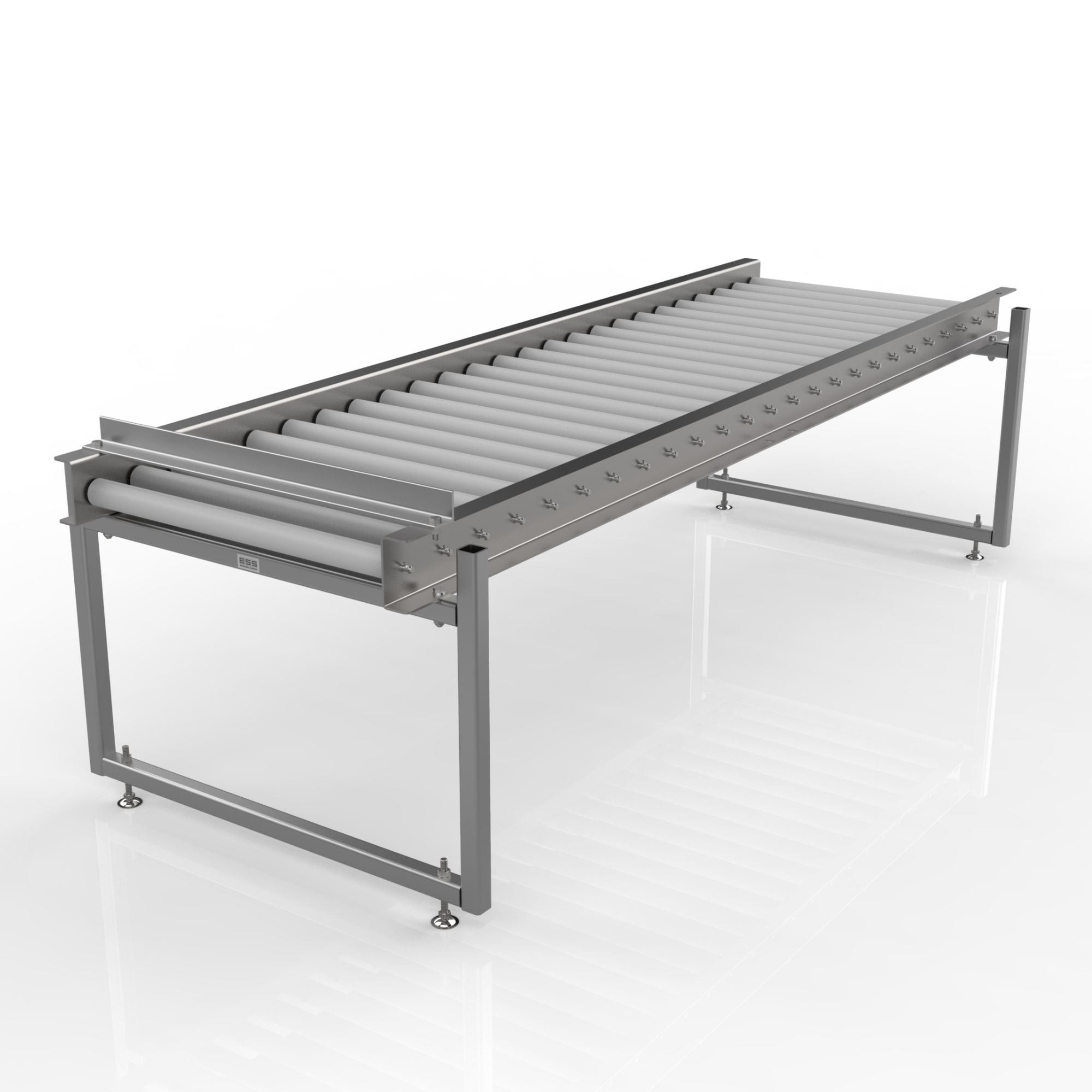
Using Autodesk Inventor, Cadrill built a comprehensive, parametric 3D CAD model of the entire conveyor assembly. The design approach focused on:
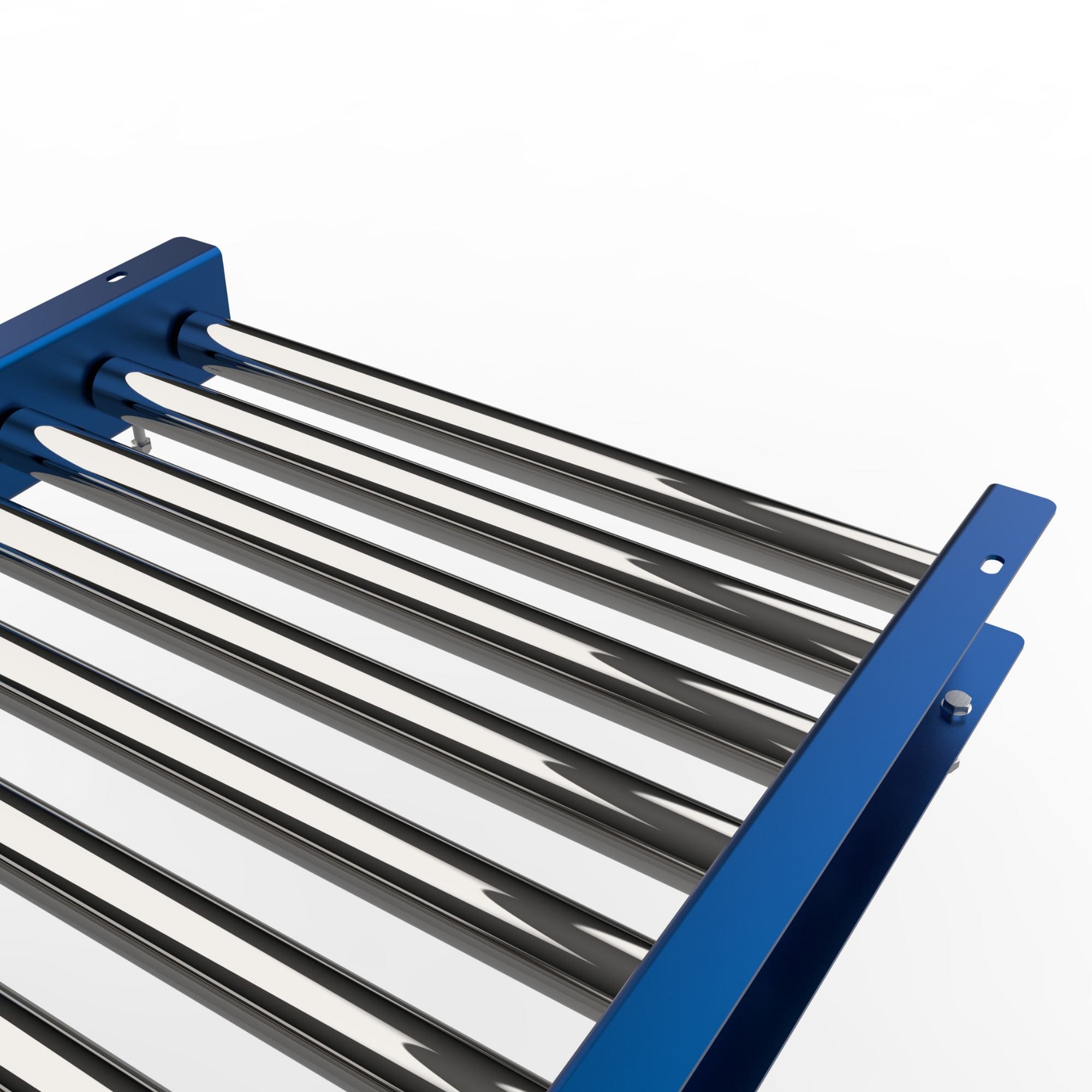
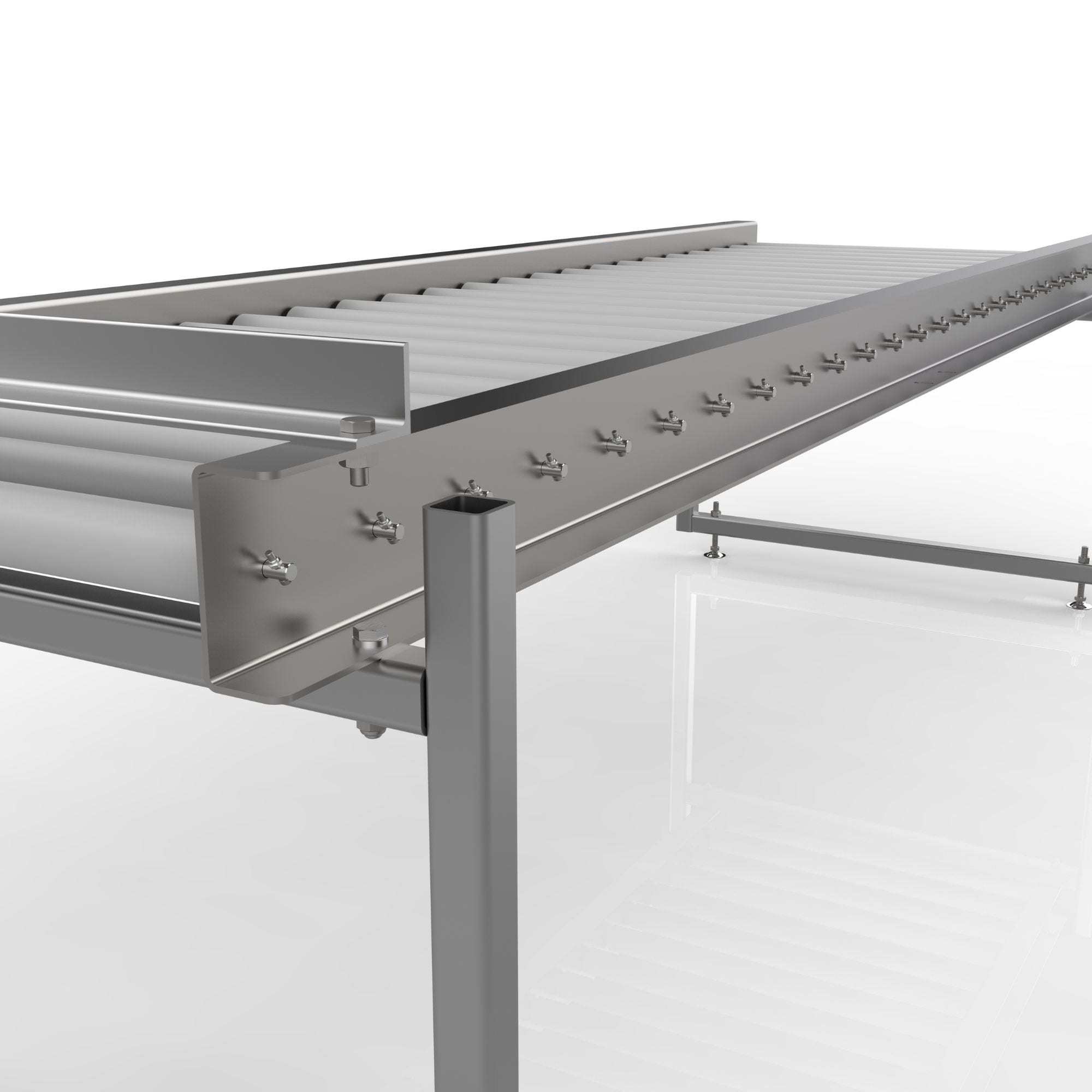
Bespoke Layout Architecture: The conveyor bed, side guides and mounting brackets were configured to navigate the plant's tight boundaries while maintaining an unimpeded product transfer path.
Sheet Metal & Weldment Detailing: All sheet-metal side panels, brackets and drip trays were developed with exact bend reliefs, corner notches and fold lines to suit standard press-brake tooling. Stainless-steel weldment assemblies were structured so that welders had clear joint access during workshop fabrication.
Roller & Drive Integration: Precise roller mounting brackets, shaft retainers and drive end interfaces were modelled in 3D to ensure accurate alignment between drive sprockets, rollers and tensioning devices.
Engineering Details & CAD Models
Manufacture-Ready Design
To allow fabricators to manufacture the conveyor accurately without ambiguity, Cadrill issued a complete set of 2D manufacturing and fabrication drawings alongside the native 3D CAD files.
The drawing package included:
- Detailed sheet-metal flat-pattern DXFs with bend deductions and bend lines.
- Fabrication assembly drawings highlighting weld types, weld locations and overall fabrication tolerances.
- Sub-assembly drawings for roller brackets, drive end mounts and support legs.
- Itemised Bills of Materials (BOM) linking every fabricated part to its parent assembly.
Project Outcome
The completed 3D CAD design and comprehensive fabrication drawings provided FMC with an accurate, site-verified conveyor solution ready for direct manufacture. Fabricators built the assembly directly from Cadrill's drawings without costly rework or on-site modifications, and the bespoke layout successfully enabled reliable product transfer through the client's restricted space.
Related Mechanical Design Services in Liverpool
If your business requires bespoke conveyor design or mechanical CAD in Liverpool, Cadrill can take your project from initial engineering concept through detailed 3D CAD, CNC machining and fabrication-ready drawings. Serving industrial clients across Liverpool, Merseyside and the North West, our engineering practice specialises in material handling systems, stainless-steel sheet-metal fabrications, precision CNC components and custom mechanical machinery.